openSUSE:JoyPi
The JoyPi is an experimental case based on the Raspberry Pi 3B/3B+/4B. More information on https://joy-it.net/en/products/rb-joypi
You can download:
Features
- DISPLAY: 7" Touchscreen Display (Resolution: 1024x600), 8x8 LED Matrix, 16x2 LED Module, 4-digit Segment Display
- CAMERA: 2MP USB Camera
- SENSORS: Light sensor, Sound sensor, Motion sensor, Ultrasonic sensor, Tilt sensor, Infrared sensor, Touch sensor, DHT11 Temperature & humidity sensor, RFID module, Tilt sensor
- BUTTONS: Programmable 4x4 button matrix, 4 independent buttons, 16 switches
- MOTORS: Servo control, servo motor, stepper motor
- OTHER MODULES: GPIO LED Indicator, Breadboard, Vibration Unit, Buzzer, Relay
- ACCESSORIES: Mini Keyboard & USB receiver, power supply, GPIO cable, microSD card, RFID chip, RFID card, USB cable, remote control, micro-HDMI adapter for RPI 4B
Setup
Hardware setup
Please follow the instructions from short manual to install the hardware properly.
Software setup
You can use any openSUSE ready to boot image for RPi3 or RPi4, depending on which board is in use on your system.
I recommend to use the XFCE image as a base. Then, you can:
- Add a non root user: log in as root/linux and start yast2 users to add a new user. You can add some group to this user: video, dialout
- Enable I2C access by following openSUSE:I2C#Load_i2c-dev_kernel_module and enable i2c-1 access by adding the following lines to /boot/efi/extraconfig.txt:
# Enable I2C access from Linux
dtparam=i2c_arm=on
# Uncomment following line to set i2c-1 baudrate to 400 000 Hz (default i2c-1 baudrate is 100 000 Hz)
# dtparam=i2c_arm_baudrate=400000
- Enable SPI access by following openSUSE:SPI#Load_spidev_kernel_module and enable spidev access by adding the following lines to /boot/efi/extraconfig.txt:
# Enable SPI access from Linux
dtparam=spi=on
- Install some usefull tools:
sudo zypper in fswebcam libgpiod i2c-tools spi-tools htop v4l-tools v4l-utils vlc python3-gpiod python3-smbus python3-spidev git
- Some tests examples are hosted on https://github.com/ggardet/joypi so you can download them with:
git clone https://github.com/ggardet/joypi
Devices
7" TouchScreen
As soon as you boot your openSUSE image, the 7" screen will be used. No configuration needs to be done. Under openSUSE is started, you can use the touchscreen as you would use a mouse.
USB camera
Check with v4l2-ctl --all that you have the USB 2.0 PC Camera: PC Camera detected.
You can take a 1280x1024 picture with:
fswebcam -r 1280x1024 --no-banner image1.jpeg
or
streamer -s 1280x1024 -f jpeg -o image2.jpeg
Or, with vlc, click on Media > Open Capture Device..., select /dev/video0 in Video device name and click on Play.
GPIO/Leds
For most pins from the 40-pin connector, you have a led to show the current state of the output.
You can switch on the led from pin7 (gpio4) for 3 seconds with:
gpioset -m time -s 3 -l gpiochip0 4=1
See openSUSE:GPIO for more details.
Touch sensor: pin11 (gpio17)
Touch sensor is on pin11 (gpio17). Get input value (0 is no touch, 1 is touching):
gpioget gpiochip0 17
Buzzer: pin12 (gpio18)
Buzzer is on pin12 (gpio18). Buzz for 1 second with:
gpioset -m time -s 1 gpiochip0 18=1
IR receiver: pin38 (gpio20)
You must plug-in the IR receiver as stated in the hardware manual. You need to remove it before closing the case.
For Raspberry Pi, you need to add the following lines to /boot/efi/extraconfig.txt:
 # Enable IR receiver on gpio20
 dtoverlay=gpio-ir,gpio_pin=20
You can check that your hardware is properly setup, by pressing some keys from the IR remote provided with the kit and check if LED connected on pin38 (gpio22) is blinking while you press the key.
Relay: pin40 (gpio21)
Relay is on pin40 (gpio21). Switch on the relay for 10 second with:
gpioset -m time -s 10 -l gpiochip0 21=1
Tilt sensor: pin15 (gpio22)
The tilt sensor allows us to detect an inclination to the right or to the left.
The tilt sensor is on pin15 (gpio22), but you need to switch ON switch number 2, on right DIP switch, the others to OFF. Read the value returned by the sensor (0 when tilt to right, 1 when tilt to left):
gpioget gpiochip0 22
Motion sensor: pin16 (gpio23)
The motion sensor is on pin16 (gpio23). Read the value returned by the sensor (0 when nothing has been detected, 1 when something moved in front of the sensor):
gpioget gpiochip0 23
The sensibility can be adjusted with a screwdriver by the potentiometer R125 in the MOTION area, near the transparent cap.
Vibrator: pin13 (gpio27)
Vibrator is on pin13 (gpio27). Switch on the vibrator for 4 second with:
gpioset -m time -s 4 gpiochip0 27=1
Step motor: pins 29,31,33,35 (gpio 5, 6, 13, 16)
The step motor is a 28BYJ-48 5VDC. In order to use it, you need to set the right DIP switches 3-6 to on, the others to off.
To move the rotor, you need to follow the following steps. Once at step 8, loop to step 1.
If you want to turn in the other direction, just go backward (from step 8 to step 1).
| Pin / GPIO | Init | Step 1 | Step 2 | Step 3 | Step 4 | Step 5 | Step 6 | Step 7 | Step 8 |
|---|---|---|---|---|---|---|---|---|---|
| A / gpio5 | 0 | 0 | 0 | 0 | 0 | 0 | 1 | 1 | 1 |
| B / gpio6 | 0 | 0 | 0 | 0 | 1 | 1 | 1 | 0 | 0 |
| C / gpio13 | 0 | 0 | 1 | 1 | 1 | 0 | 0 | 0 | 0 |
| D / gpio19 | 0 | 1 | 1 | 0 | 0 | 0 | 0 | 0 | 1 |
You need to move on 512 steps for 360° (1 full turn).
7-segment display
The 7-segment display is driven by a HT16K33 (datasheet) on i2c-1 bus, at address 0x70.
- 1st digit (from the left) is defined by register 0x00
- 2nd digit (from the left) is defined by register 0x02
- the 2 dots (hours and minutes separation) is defined by register 0x04 (set it to 0x00 (off) or 0x02 (on))
- 3rd digit (from the left) is defined by register 0x06
- 4th digit (from the left) is defined by register 0x08
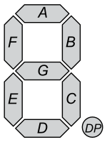
| Name | DP | G | F | E | D | C | B | A |
| Bit | 7 | 6 | 5 | 4 | 3 | 2 | 1 | 0 |
For each digit, the value of the register set a segment. A value of 0 set the segment on, a value of 1 set the segment off.
So, if you want to display a 0, you need to set A,B,C,D,E,F to on, which would be binary value b0011_1111 which is 0x3F in hexadecimal. So, for the 2nd digit, it would be:
i2cset -y 1 0x70 0x02 0x3F
And you have special registers to enable/disable the 7-segment and to make it blink.
- Enable display (no blink): write special command 0x81
i2cset -y 1 0x70 0x81
- Disable: write special command 0x80
i2cset -y 1 0x70 0x80
- Blink:
- at 2 Hz: write special command 0x83
i2cset -y 1 0x70 0x83
- at 1 Hz: write special command 0x85
i2cset -y 1 0x70 0x85
- at 0.5 Hz: write special command 0x87
i2cset -y 1 0x70 0x87
RFID-RC522 (SPI0.0)
- MFRC522 datasheet
- MFRC522-python (untested)
See openSUSE:SPI for more information about SPI.
8x8 Led matrix (SPI0.1)
The 8x8 Led matrix is driven by a MAX7219 (datasheet) connected on SPI0.1 (Bus 0, ChipSelect 1), which runs at 10 MHz max.
Test display by switching on all LEDs (test mode):
echo -n -e "\x0F\x01" | spi-pipe -d /dev/spidev0.1 -s 10000000 | xxd
And switch back to normal mode:
echo -n -e "\x0F\x00" | spi-pipe -d /dev/spidev0.1 -s 10000000 | xxd
Initialization for LED matrix operation:
 echo -n -e "\x0C\x01" | spi-pipe -d /dev/spidev0.1 -s 10000000 | xxd    # Normal operation
 echo -n -e "\x09\x00" | spi-pipe -d /dev/spidev0.1 -s 10000000 | xxd    # No decoding
 echo -n -e "\x0A\x0F" | spi-pipe -d /dev/spidev0.1 -s 10000000 | xxd    # Intensity: max 0x0F
 echo -n -e "\x0B\x07" | spi-pipe -d /dev/spidev0.1 -s 10000000 | xxd    # Make use of all leds
 # Switch off all leds
 echo -n -e "\x01\x00" | spi-pipe -d /dev/spidev0.1 -s 10000000 | xxd    # Row 1
 echo -n -e "\x02\x00" | spi-pipe -d /dev/spidev0.1 -s 10000000 | xxd    # Row 2
 echo -n -e "\x07\x00" | spi-pipe -d /dev/spidev0.1 -s 10000000 | xxd    # Row 3
 echo -n -e "\x04\x00" | spi-pipe -d /dev/spidev0.1 -s 10000000 | xxd    # Row 4
 echo -n -e "\x05\x00" | spi-pipe -d /dev/spidev0.1 -s 10000000 | xxd    # Row 5
 echo -n -e "\x06\x00" | spi-pipe -d /dev/spidev0.1 -s 10000000 | xxd    # Row 6
 echo -n -e "\x07\x00" | spi-pipe -d /dev/spidev0.1 -s 10000000 | xxd    # Row 7
 echo -n -e "\x08\x00" | spi-pipe -d /dev/spidev0.1 -s 10000000 | xxd    # Row 8
Now you can set each led of each row. To set the last 4 leds of 1st row:
echo -n -e "\x01\x0F" | spi-pipe -d /dev/spidev0.1 -s 10000000 | xxd
To set the first 4 leds of 2st row:
echo -n -e "\x02\xF0" | spi-pipe -d /dev/spidev0.1 -s 10000000 | xxd
There is also a python script to show how to use it in python: https://github.com/ggardet/joypi/blob/master/joypi_led_matrix.py
You will need python3-spidev package.
See openSUSE:SPI for more information about SPI.
LCD 16x2 (i2c-1 0x21)
The 16x2 LCD is on i2c-1 bus, address 0x21. It seems to be similar to I2C 16x2 Arduino LCD Display Module, and seems to be driven by a MCP23008 with the following connections:
| PCA8574 pin | P7 (input/output) | P6 (input/output) | P5 (input/output) | P4 (input/output) | P3 (output) | P2 (output) | P1 (output) | P0 (output) |
| LCD pin (4-bit mode) | B7 | B6 | B5 | B4 | BT (backlight) | E | R/W | RS |
Set all gpio for LCD to output:
i2cset -y 1 0x21 0x00 0x00
Set BT to 1 to enable backlight:
i2cset -y 1 0x21 0x09 0x80
Set BT to 0 to disable backlight:
i2cset -y 1 0x21 0x09 0x00
See openSUSE:I2C for more information about I2C.
Light sensor (i2c-1 0x5C)
The i2c light sensor is on i2c-1, address 0x5C. It seems to be a Rohm BH1750FVI (datasheet). You can get the raw value from register 0x20 with:
i2cget -y 1 0x5c 0x20 w
To get a readable value in lux, you need to perform the following operation: (upper byte + 256 * low byte) / 1.2. So, if you get:
0x9c00
0x9c is 156 in decimal, 0x00 is 0 in decimal. So, you have (156 + 256*0)/1.2 = 130 lx
There is also a python script to print the lx value directly: https://github.com/ggardet/joypi/blob/master/joypi_light_sensor.py
You will need python3-smbus package.
See openSUSE:I2C for more information about I2C.
Temperature and humidity sensor (1-wire on gpio4, pin7)
In your /boot/efi/extraconfig.txt file, you need to add the following line to enable 1-wire interface (on the gpio4) on boot:
 # Enable 1-wire interface on gpio4
 dtoverlay=w1-gpio
Once rebooted, check on /sys/bus/w1/devices/ if you have w1_bus_master1 and maybe also slave devices.
See openSUSE:1-wire for more information about 1-wire interface.