openSUSE:1-wire
Enable
1-wire interface can be used with a real 1-wire master interface such as mxc-w1, omap-hdq and others, or on a GPIO. On a real 1-wire master interface, you have nothing to do, as the interface is already registered in your devcie tree.
If you want to use w1-gpio driver on a regular GPIO, you need update your device tree to add the w1-gpionode with required information, including GPIO number.
For Raspberry Pi (1, 2, 3), you need to add the following lines to your /boot/efi/extraconfig.txt file, to enable 1-wire interface (on the gpio4) on boot:
 # Enable 1-wire interface on gpio4 (default if ,gpiopin=X is omitted)
 dtoverlay=w1-gpio,gpiopin=4
Interaction using /sys fs
Check slave devices
By default, the w1 bus is probed continuously.
You can check the number of slave devices found with the following command:
cat /sys/bus/w1/devices/w1_bus_master1/w1_master_slave_count
And you also have slave devices found in /sys/bus/w1/devices folder.
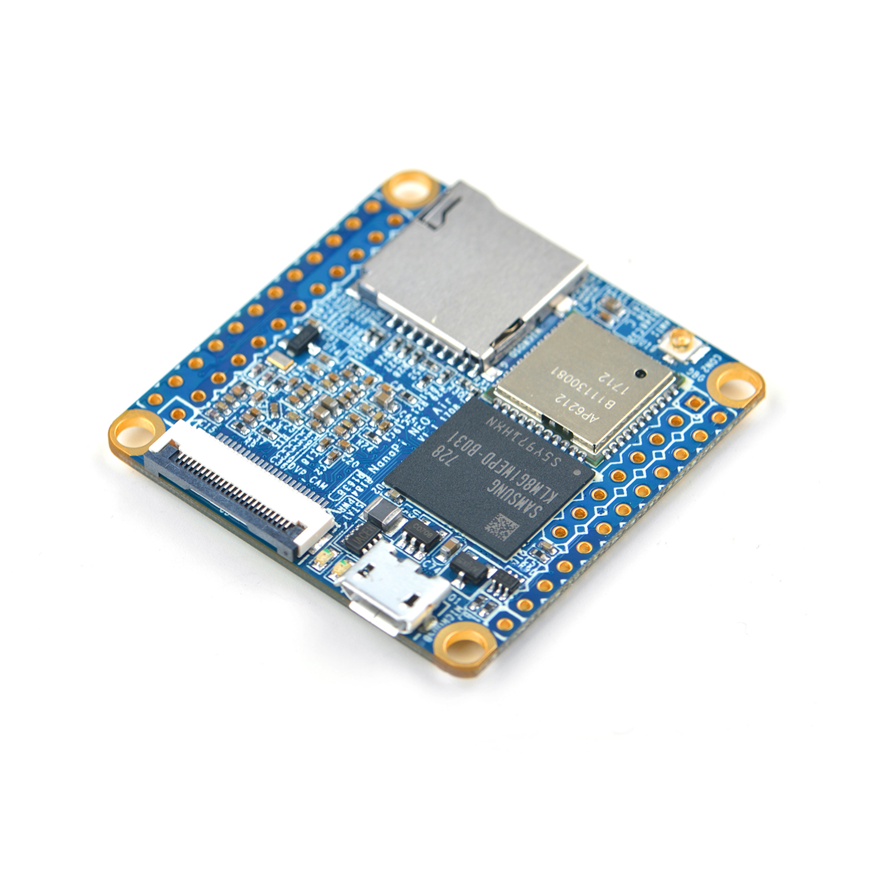
Nanopi Neo Air
Reading 1-wire sensors, in my case DS18x20 temperature devices, requires a little more work. What I describe here is based on the Leap 15.0 JeOS image for the Nanopi Neo, which requires a few minor alterations to also work on the Nanopi Neo Air. In the following I will assume you have a working openSUSE installation on your Nanopi Neo Air. I will describe the procedure step by step, without many explanations - I assume your priority is to read your 1-wire devices, understanding the details is secondary and will come later.
Brief summary
To access the 1-wire devices with your Nanopi Neo, you need to update the device tree, the DTB. I recommend you start with a more comprehensive DTB than the one from the openSUSE JeOS, which is a bit minimal. As a starting point, I use the DTB from the FriendlyCore e-flasher image. (you have to anyway, to get the Wifi interface to work).
Step-by-step
(a) You start by decompiling the DTB using "dtc".
dtc -I dtb -O dts -o <your.dts> <your.dtb>
(b) Using your favourite editor you edit the device tree source and you look for the entry "pinctrl@01c20800" and add a label "gpio0:" :
gpio0:pinctrl@01c20800
pinctrl@01c20800 is the gpiochip0, you can find this e.g. here: /sys/class/gpio/gpiochip0
(c) in this section, for instance above the 'csi' entry, add the following:
ds1820_pins:w1_pins@0 {
label = "Dallas 1-wire";
pins = "PG11";
function = "gpio_in";
pull = <0x1>;
};
Above, I am using GPIO11 and indicating it has an external pull-up resistor.
(d) towards the end of the source file, add this node:
onewire {
compatible = "w1-gpio";
pinctrl-names = "default";
pinctrl-0 = <&ds1820_pins>;
gpios = <&gpio0 0x0 203 0x1>;
status = "okay";
};
I added it after the "leds" node. "203" is the Linux number for GPIO11.
(e) compile a new dtb:
dtc -b 0 -@ -I dts -O dtb your-new.dts >/boot/dtb/your-new.dtb
(f) adjust your boot-script as necessary
(g) amend /etc/modprobe.d/99-local.conf, and add this line:
options w1-therm strong_pullup=2
(h) reboot.
Result
When you have come this far and you have hooked up a DS18x20 sensor, you should something like this under /sys/bus/w1/devices/ :
nano3:~ # l /sys/bus/w1/devices/
total 0
drwxr-xr-x 2 root root 0 Jan 10 10:21 ./
drwxr-xr-x 4 root root 0 Sep 27 11:06 ../
lrwxrwxrwx 1 root root 0 Sep 27 11:07 28-0000085bd222 -> ../../../devices/w1_bus_master1/28-0000085bd222/
lrwxrwxrwx 1 root root 0 Sep 27 11:07 28-0000092a9a2b -> ../../../devices/w1_bus_master1/28-0000092a9a2b/
lrwxrwxrwx 1 root root 0 Dec 30 19:49 28-00000a4877fa -> ../../../devices/w1_bus_master1/28-00000a4877fa/
lrwxrwxrwx 1 root root 0 Jan 10 10:21 w1_bus_master1 -> ../../../devices/w1_bus_master1/
"28-0000085bd222" is a type 28 device (DS18B20), "0000085bd222" is the unique 48-bit identifier. You can read a device by simply:
cat /sys/bus/w1/devices/28-0000085bd222/w1_slave
da fe 4b 46 7f ff 06 10 37 : crc=37 YES
da fe 4b 46 7f ff 06 10 37 t=-18375
The above means:
crc check positive, temperature is -18.375C.
Real life example
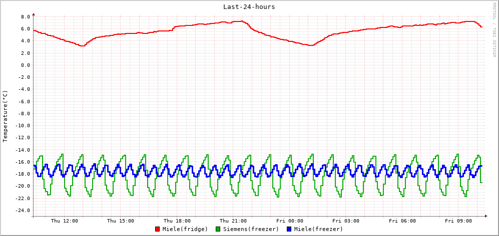
Using what I have described here, I monitor the temperature of a refrigerator and two deep freezers in our basement:

